Air Quality Monitoring
1. What You Will Build
In this tutorial, you will learn how to build Air Quality Monitoring using Arduino.
By the end of this tutorial, your project will be able to:
Measure dust concentration in the air.
Calculate the dust density in mg/m³.
Display the air quality status on the Serial Monitor.
2. What You Will Learn
After completing this tutorial, you should understand:
How to connect the GP2Y1010AU0F dust sensor to an Arduino Uno.
How to read analog data from the dust sensor.
How to convert the sensor output voltage into dust density.
How to classify air quality based on the measured dust density.
How the code works step by step
3. Components Needed
No. | Component | Quantity |
1 | Arduino | 1 |
2 | GP2Y1010AU0F Dust Sensor | 1 |
3 | Resistor 150Ω | 1 |
4 | Capacitor 220µF | 1 |
5 | Jumper wires | Several |
6 | Breadboard | 1 |
7 | USB cable | 1 |
4. Software Needed
Use the tools below depending on your board.
Board | Software |
Arduino | Arduino IDE |
Libraries Needed
No libraries needed
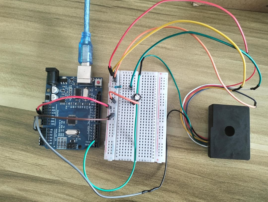
5. Circuit Connection
Connect the components as shown below.
Component Pin | Connect To |
VCC (Red) | 5V |
GND (Yellow) | GND |
Output pin (Black) | GPIO A0 |
LED Signal (Green) | GPIO 2 |
LED GND (Blue) | GND |
V-LED (White) | Between resistor and capacitor (+) |
Capasitor 220µF(-) | GND |
Resistor 150Ω | 5V |
Wiring Steps
Connect VCC of GP2Y1010AU0F Dust Sensor to 5V on the board.
Connect GND of GP2Y1010AU0F Dust Sensor to GND on the board.
Connect Output pin to GPIO A0.
Connect LED Signal pin to GPIO 2.
Connect LED GND pin to GND on the board.
Connect V-LED pin between resistor and capacitor (+).
Connect capasitor(-) pin to GND on the board.
Connect resistor pin to 5V on the board.
Double-check all wiring before powering the board.
Circuit Diagram

6. Code
const int dustPin = A0;      // Sensor output
const int ledPin = 2;        // Sensor LED control

const int samplingTime = 280;    // microseconds
const int deltaTime = 40;        // microseconds
const int sleepTime = 9680;      // microseconds

float adcValue = 0;
float voltage = 0;
float dustDensity = 0;

void setup()
{
  Serial.begin(9600);

  pinMode(ledPin, OUTPUT);
  digitalWrite(ledPin, HIGH);

  Serial.println("==========================================");
  Serial.println("      GP2Y1010AU0F DUST SENSOR TEST");
  Serial.println("==========================================");
  Serial.println();
}

void loop()
{
  // Turn ON the sensor LED
  digitalWrite(ledPin, LOW);
  delayMicroseconds(samplingTime);

  // Read analog value
  adcValue = analogRead(dustPin);

  delayMicroseconds(deltaTime);

  // Turn OFF the sensor LED
  digitalWrite(ledPin, HIGH);

  delayMicroseconds(sleepTime);

  // Convert ADC value to voltage
  voltage = adcValue * (5.0 / 1024.0);

  // Calculate dust density
  dustDensity = 0.17 * voltage - 0.10;

  // Prevent negative values
  if (dustDensity < 0)
  {
    dustDensity = 0;
  }

  // Display results
  Serial.println("==========================================");
  Serial.print("ADC Value      : ");
  Serial.println(adcValue, 0);

  Serial.print("Output Voltage : ");
  Serial.print(voltage, 3);
  Serial.println(" V");

  Serial.print("Dust Density   : ");
  Serial.print(dustDensity, 3);
  Serial.println(" mg/m3");

  Serial.print("Air Quality    : ");

  if (dustDensity < 0.10)
  {
    Serial.println("CLEAN");
  }
  else if (dustDensity < 0.30)
  {
    Serial.println("MODERATE");
  }
  else
  {
    Serial.println("HIGH DUST LEVEL");
  }

  Serial.println("==========================================");
  Serial.println();

  delay(1000);
}
7. Upload / Run the Project
Connect the board to your computer using USB.
Open the code in Arduino IDE.
Select the correct board.
Select the correct port.
Click Upload.
Open the Serial Monitor if needed.
8. Expected Result
When the project is working correctly:
The Serial Monitor displays the ADC value, output voltage, and dust density.
The air quality is shown as CLEAN, MODERATE, or HIGH DUST LEVEL.
The readings update every second
9. Troubleshooting
Problem | Possible Fix |
Board not detected | Check USB cable, driver, board, and port selection |
Code upload failed | Select the correct board and COM port |
Sensor not working | Check VCC, GND, and signal pin wiring |
Output not turning on | Check pin number and component polarity |
Wrong readings | Check sensor voltage and calibration |